Close your eyes, take a deep breath and fast forward four years when Trump’s administration will be roundly rejected. Feel in your body the hope that will overwhelm you. Conjure up your future restored faith in humanity when people from all walks of life stand together against hate.
I have never felt so pessimistic and defeated than in the last week. The press will normalize him, the Democratic minority will indulge him, and voters will grow apathetic and disengaged. No matter the scandals, past and future, that will embroil Trump and his goons; they will continue to consolidate power. He can’t be “exposed” for who he really is, it has been in plain sight all along.
Trump and his kind will not go away, and the establishment is not coming back to rescue us. Cory Booker, Joe Biden, Michelle Obama, or any other Democrat star will not pull us out of this tailspin. They will try to convince us, as Hillary tried, that the electorate will embrace a competent centrist. They won’t, and the right will only grow in influence. This nightmare can endure for decades.
The only thing that will save us from a populist racist oligarch demagogue is a populist anti-racist anti-neoliberal progressive with a mobilized movement behind them and serious contenders up and down the ticket.
Before Trump got elected, we already had our work cut out for us: Black Lives Matter, equitable health care, reproductive rights, equal pay, housing justice, clean water, criminal justice, equitable education, prison abolition, gender justice, free Palestine, voting rights, indigenous rights, refugee rights, migrant rights, campaign finance reform, friggin’ climate change and climate justice.
We don’t get to put those issues aside until the next Obama is elected and we clear up our heads. We *amplify* those struggles and use their leverage to restore democracy and propel us forward to a revolution. We don’t have four years, we need to have our ducks in a row for the midterms in two.
Am I being too preachy? I’m sorry. This is my catharsis. It’s the take-charge method Penny Simkin recently taught us in class.
There are countless people who’s security and future are called into question with this turn of events. If you, like me, are shrouded in privilege – don’t let it paralyze you. Don’t be an ally, be an actor. Own this struggle. I would bring up that famous Murri quote, but you already know it.
I know many smart, strategic, and dedicated people who work on this stuff every day, and I am so humbled and thankful they do this work and the sacrifices they make.
We are anticipating a wonderful life transition soon (more on that later?), as the dust settles from this election and as we find our stride as a family I look forward to working on our liberation with you all.
Close your eyes, take a deep breath, and borrow just a little bit of the hope and restored faith you will feel in four years.
- Problem Statement:
- In today’s fast-paced world, while juggling work and personal life, sometimes we need to know what time it is.
- Solution:
- A chronometer you can hang on the wall.
Wake up people. Clocks are the future. Embrace progress.
Hello, my name is Eitan. I am a clock maker.
Over the past year I have spent nights and weekends designing gear trains, circuit boards, soldering and writing software. The result is a clock. Not just any clock, it is a smart clock that could tell you what time it is on demand. It is internet-connected so you can remotely monitor what time it is in your home.
It is powered by three stepper motors, 3 hall effect sensors, and a miniature computer. It also ticks.
 The future of time telling.
Why? Because in my hubris I thought it would be an easy weekend project, and then things got out of hand.

Gears
My first gear boxes were pretty elaborate, with different gear ratios for each motor/hand. I probably spent the most time in the design/print cycle trying to come up with a reliable solution that would transfer the torque from 3 separate motors to a single axis. I ended up with something much simpler, a 2:1 gear ratio for all hands.
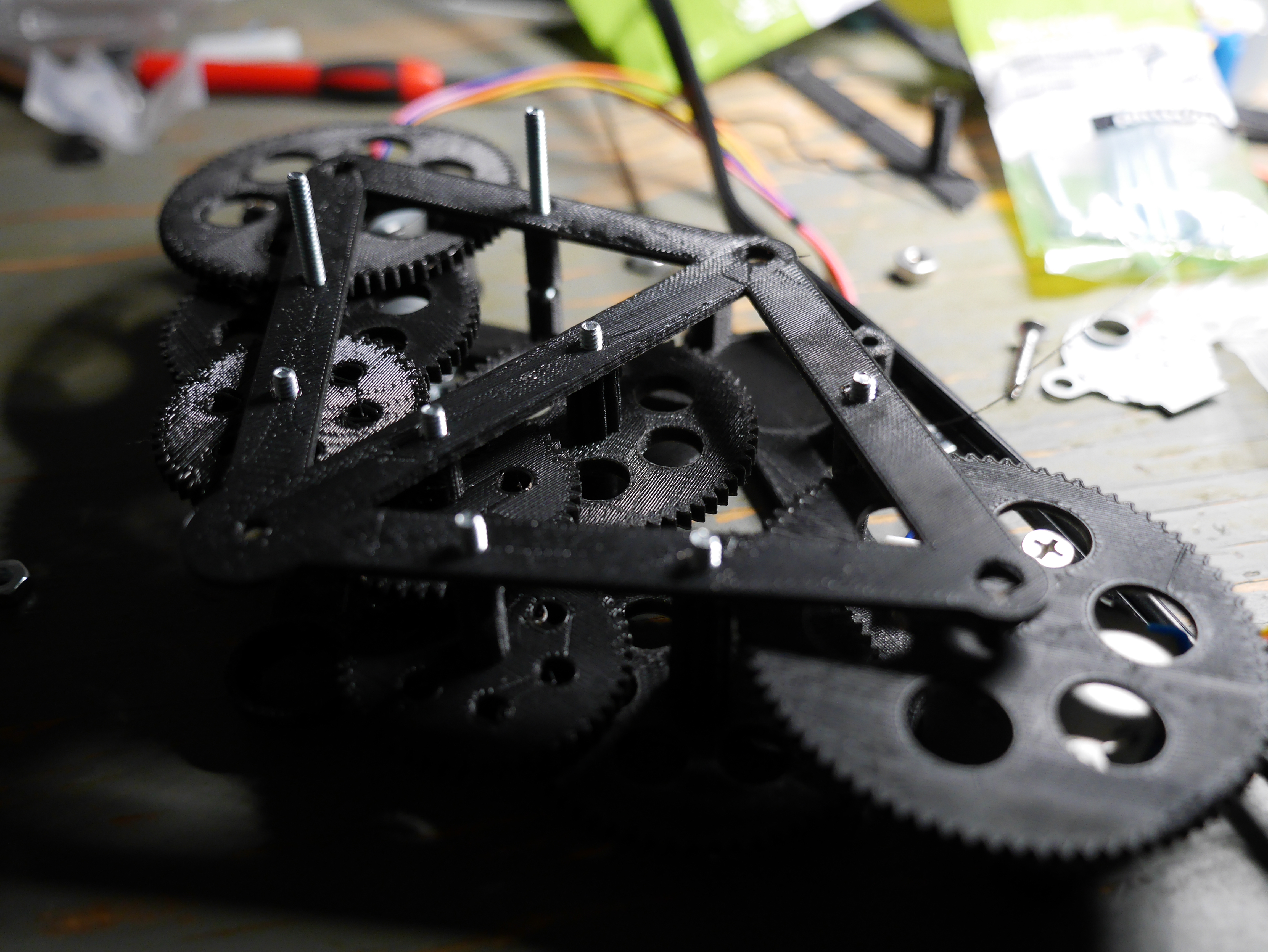 An example of an early super elaborate and huge gear box.
 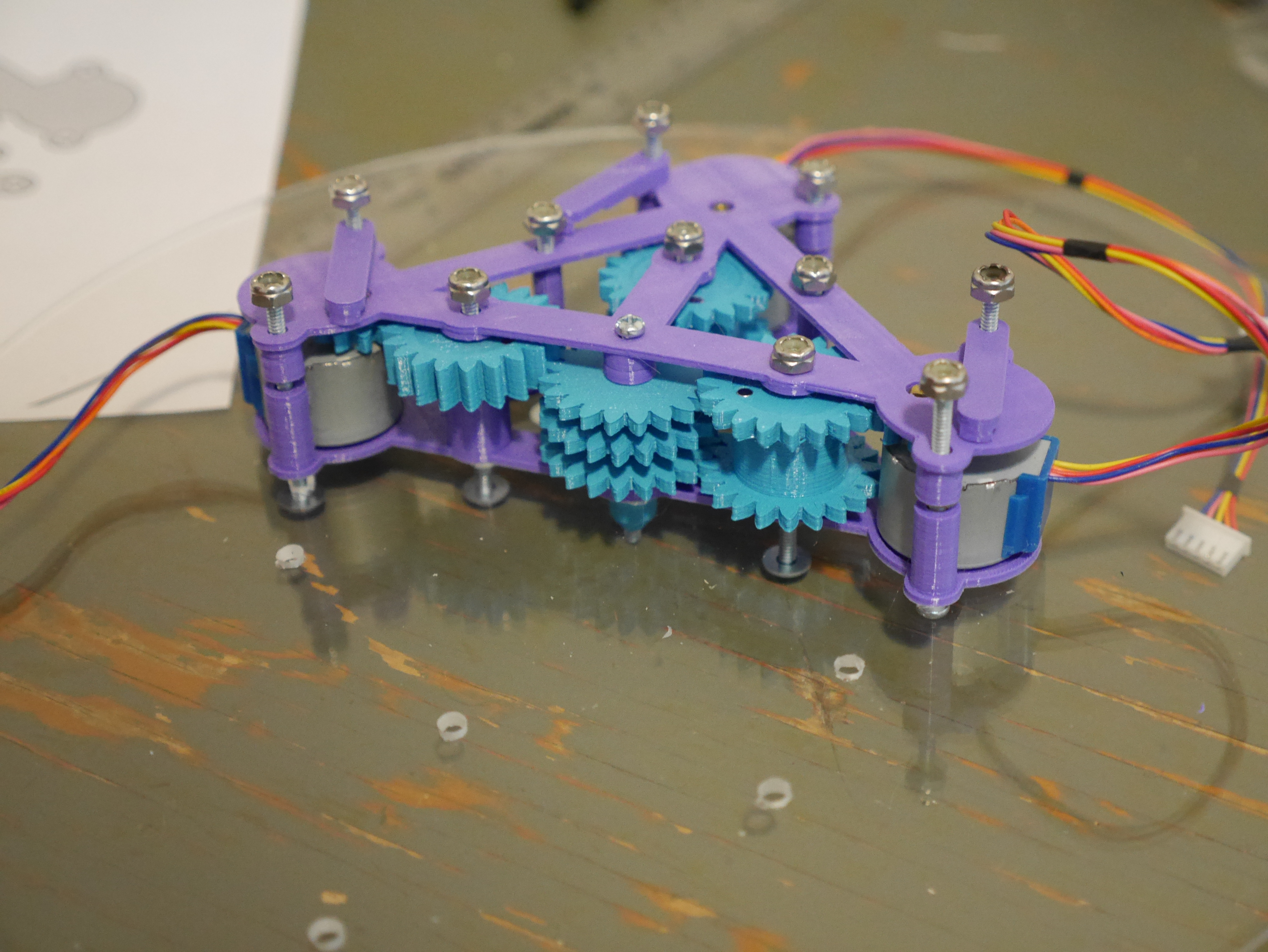 My final design.
Limit Switches
Another challenge I struggled with was how would the software know where each hand is at any given time? A stepper motor is nice because it has some predictability. Each one of its steps is equal, so if you know that a step size is 6 degrees, it will take 60 steps to complete a rotation. In our case, this isn’t good enough, because:
- The motor is not 100% guaranteed to complete each step. If there is too much resistance on it, it will fail. I struggled to design a perfect gear box that won’t ever make things hard for the motors, but there will be a bad tooth every once in a while that will jam the motor for a step or two.
- The motor I chose for this project is the 28BYJ-48, mainly because it is cheap and you can get a pack of 5 from amazon with drivers for only $12. Its big drawback is that there is no consensus on what the precise step size is. Internally the motor has 32 steps per revolution (11.25 degrees per step). But it has a set of reduction gears embedded in it that make the steps per revolution something like 2037.886. Not a nice number and, more importantly, not good for clocks that risk drifting out of precision.
- When the clock is first turned on, it has no way to know the initial position of each hand.
I decided to solve all this with limit switches. If the clock hands somehow closed a circuit at the top of each rotation, we would at least know where “12 o’clock” is and we will have something to work with. I thought about using buttons, metal contacts and the likes. But I didn’t like the idea of introducing more wear on a delicate mechanical system: how many times will the second hand brush past a contact before screwing it up?
So, I went with latching hall effect sensors. The basic concept is magnets. The sensor will open or close a circuit depending on what pole of a magnet is nearby. I glued tiny magnets at opposite ends of the gears, and by checking the state of the a sensor circuit after every motor step you can tell if we just got to 6 o’clock or 12 o’clock.
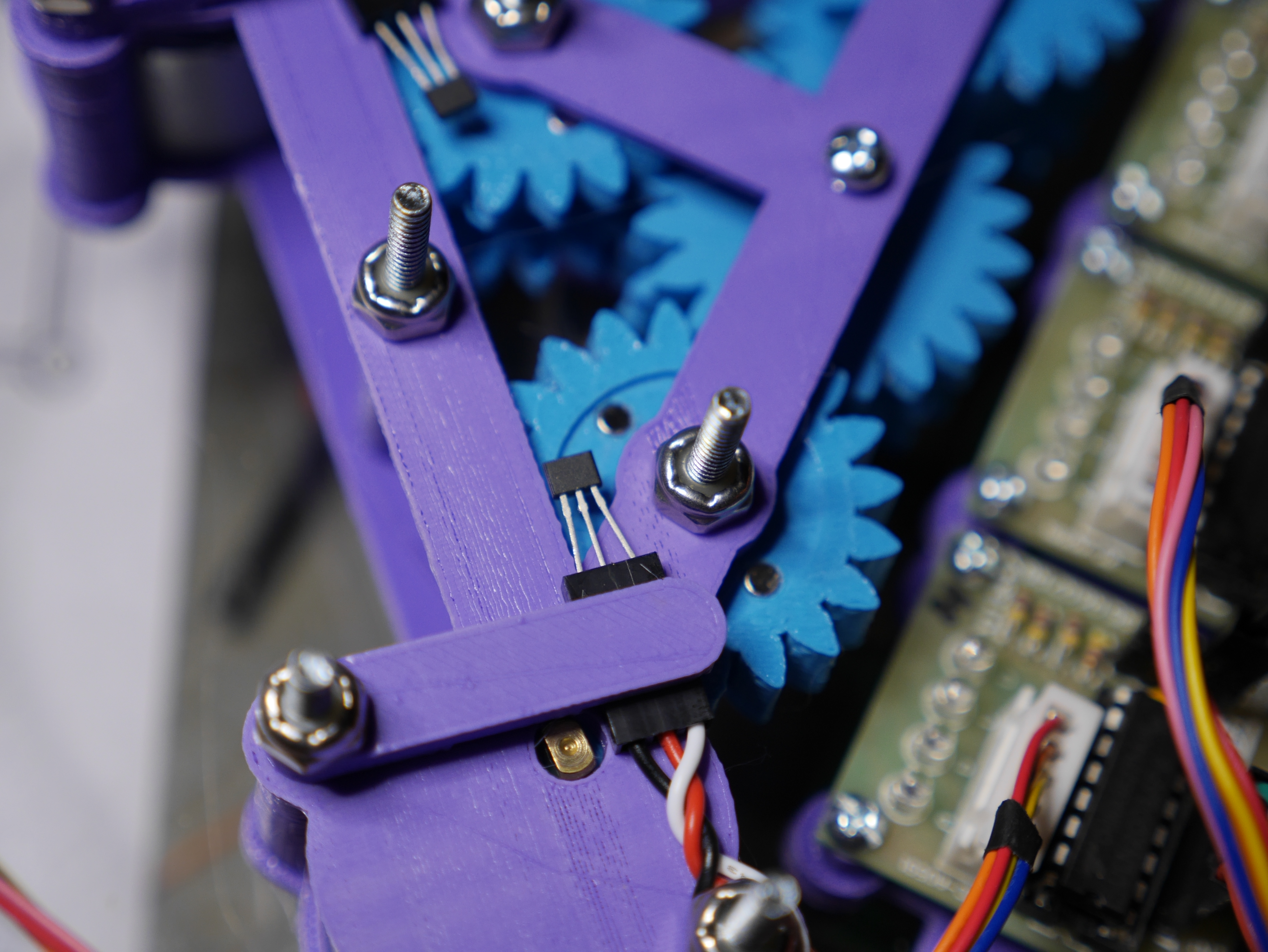 Two magnets on opposite sides of the gear, and the hall effect sensor clamped just above the gear to detect polarity changes.
Circuits
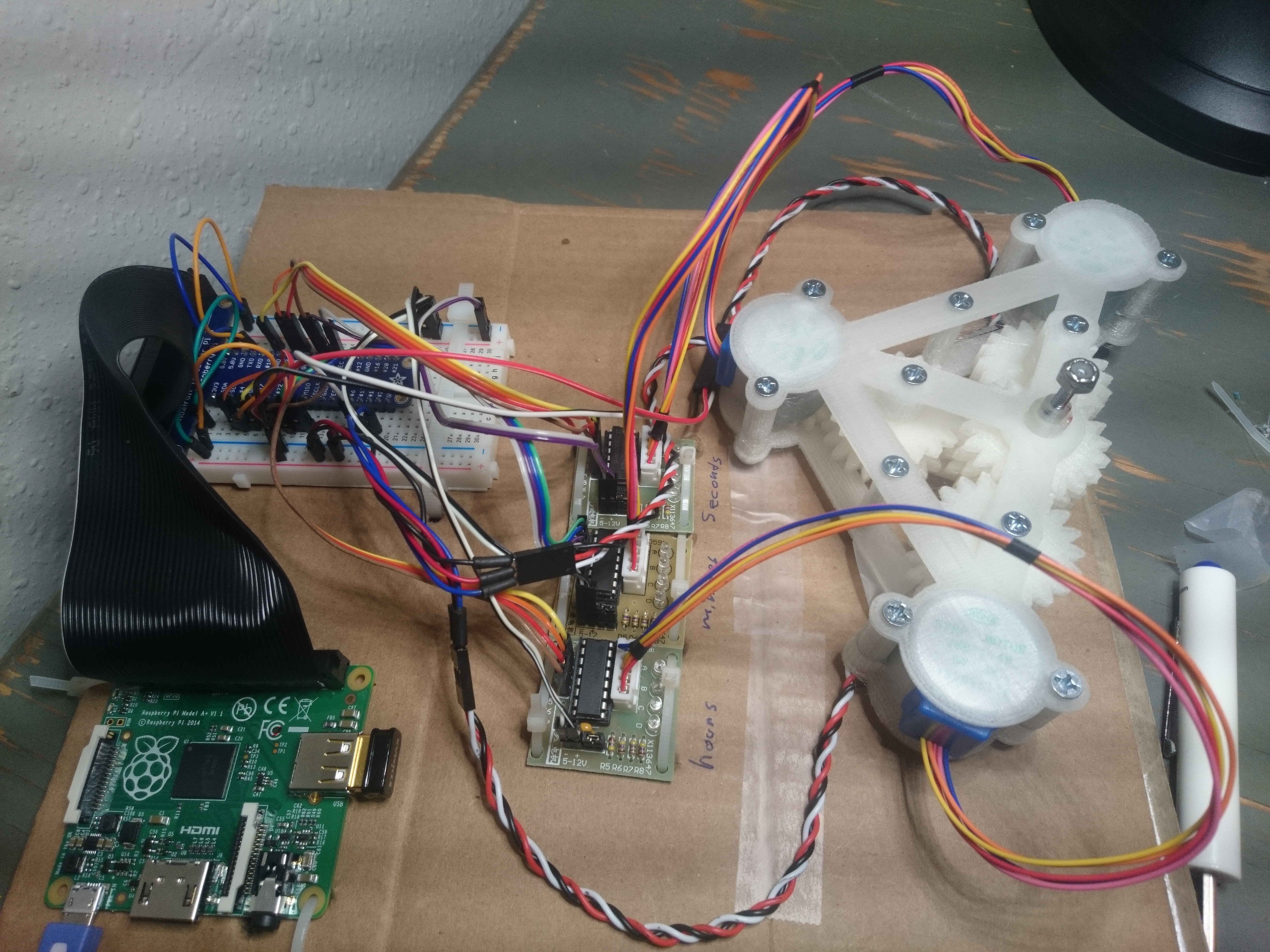
Electricity is magic to me, I really don’t understand it. I learned just enough to get this project going. I started by reading Adafruit tutorials and breadboarding. After assembling a forest of wires, I finally got a “working” clock. I wanted the final clock to be more elegant than this:
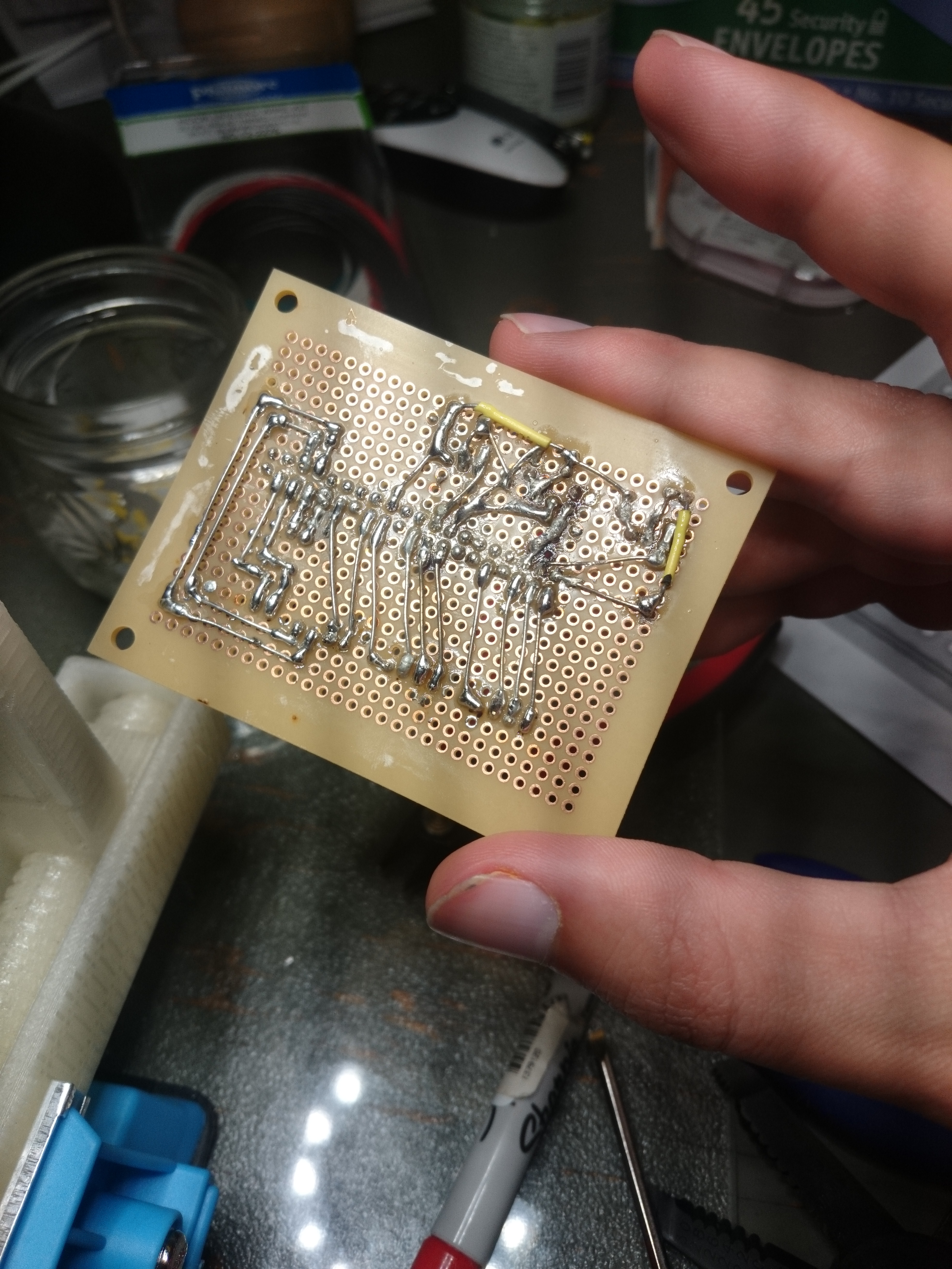
With some graph paper, I sketched out how I can arrange all of the circuits on a perf board and went to work soldering, after inhaling a lot of toxic fumes and leaving some of my skin on the iron I got this:
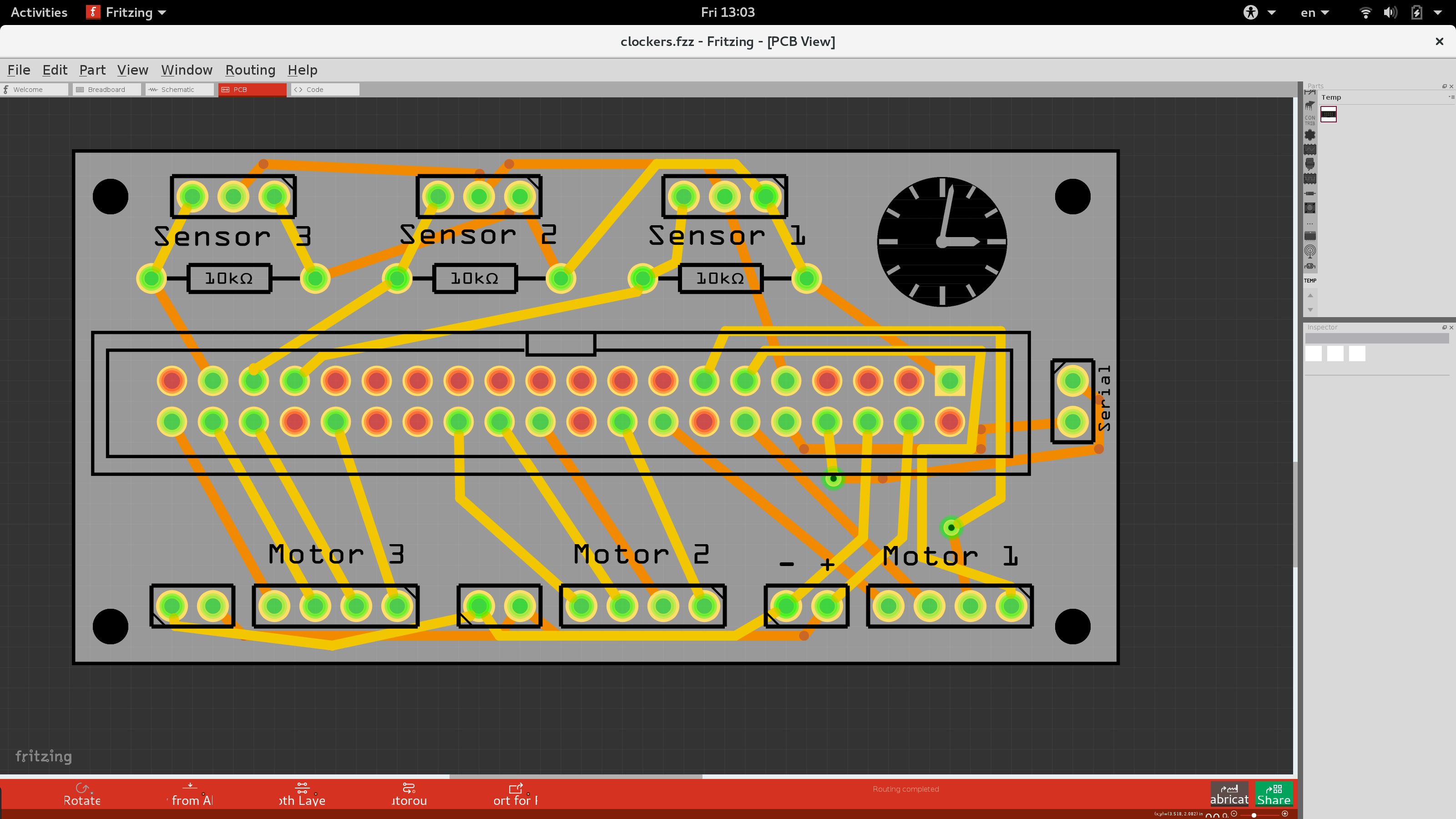
I was happy with the result, but it could be prettier. Plus, I would never put myself through that again. I wanted to make this process as easy as possible. So I decided to splurge a bit, I redesigned the board using Fritzing:
…and ordered PCB prints from their online service. After a month or so I got these in the mail:
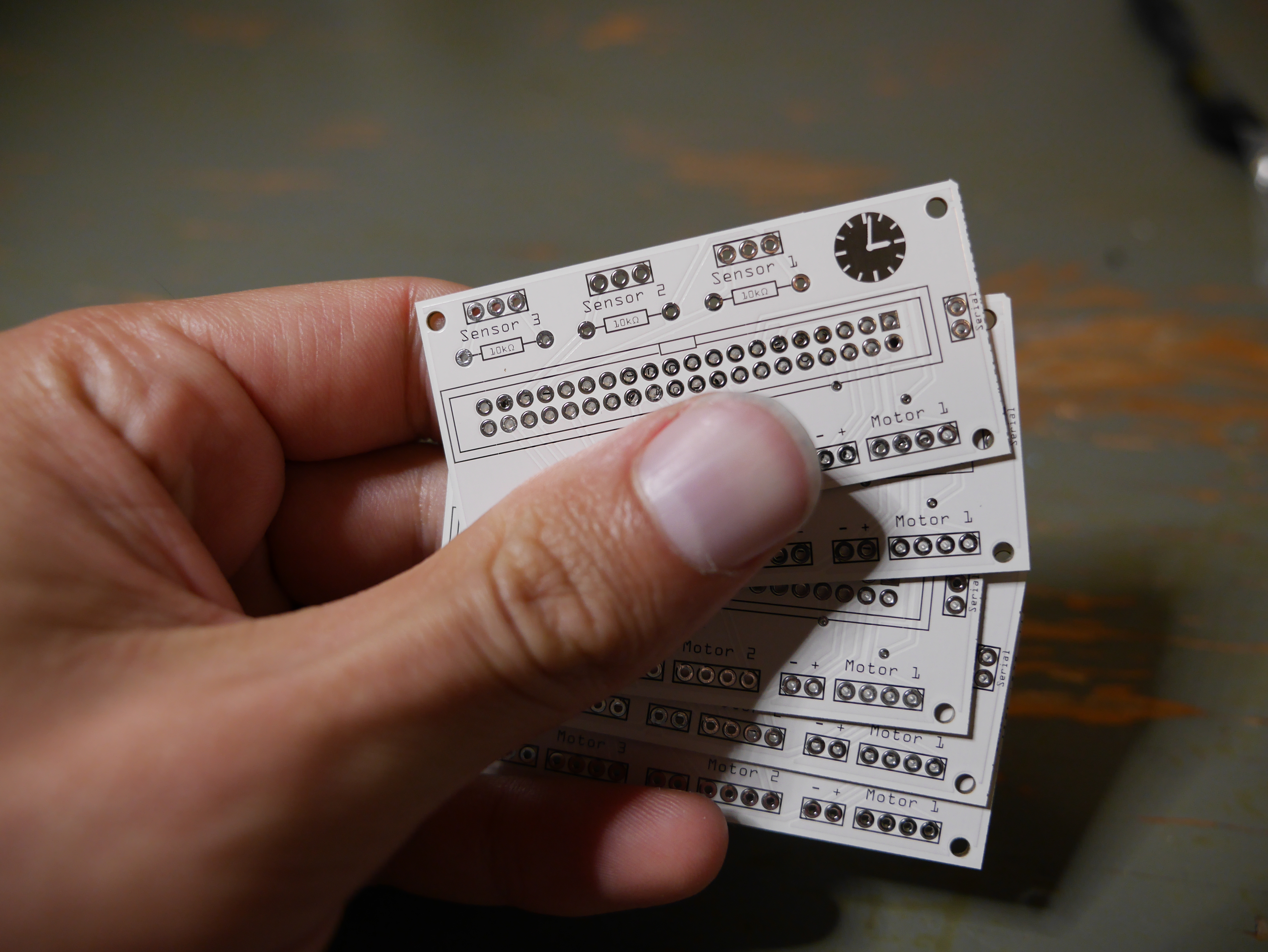 Custom PCBs printed in Berlin!
Soldering on components was a breeze…
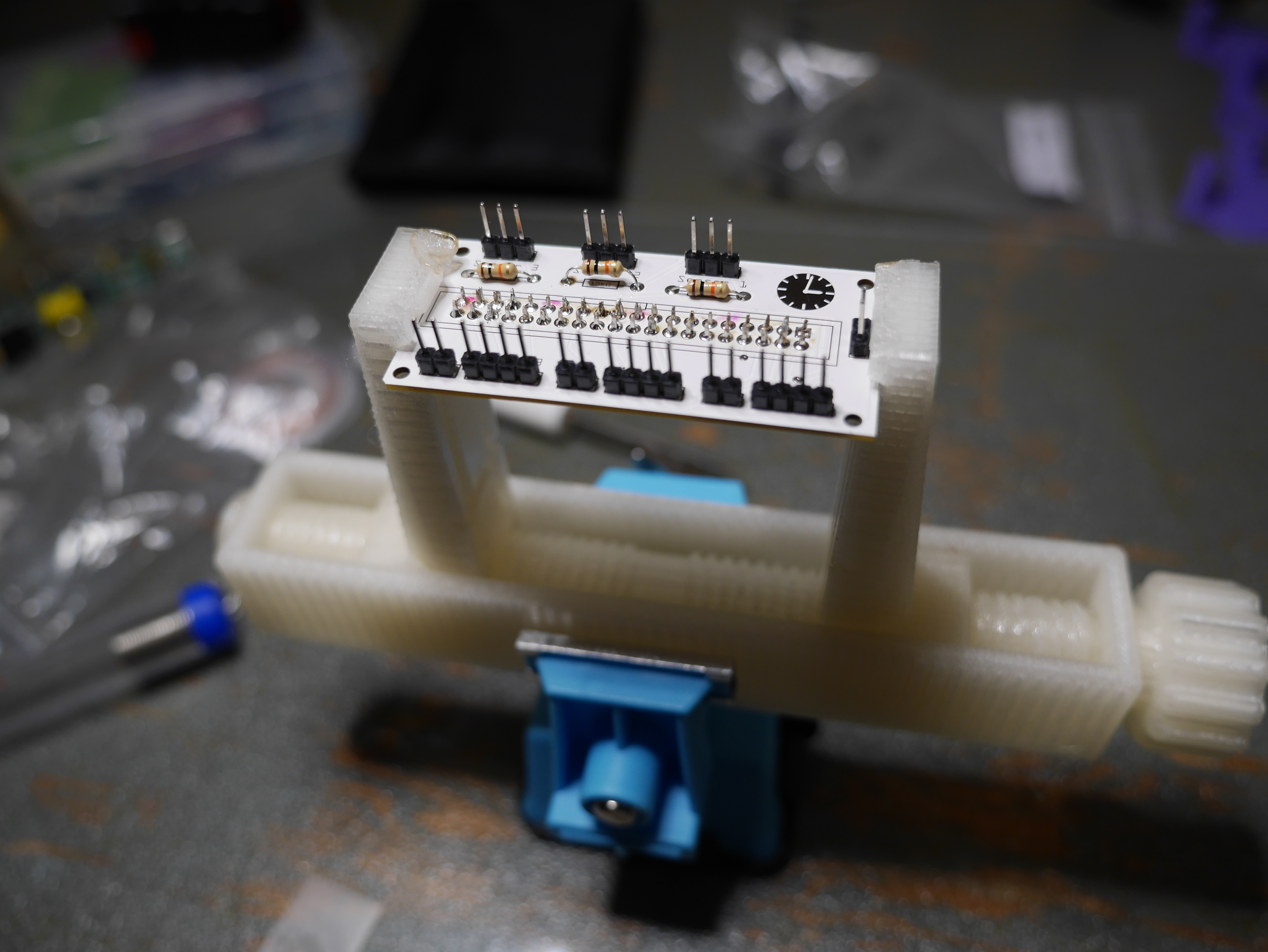 PCB with jumper headers and resistors.
Software
Software is my comfort zone, you don’t get burnt, electrocuted, or spend a whole day 3D printing just to find out your design is shit. My plan was to compensate for all the hardware imperfection in software. Have it be self-tuning, smart and terrific.
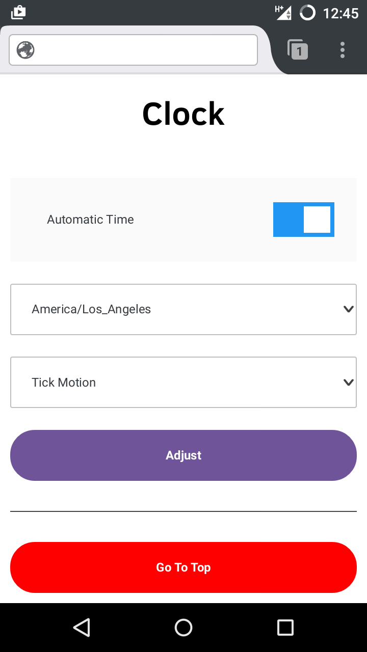
I chose to have NodeJS drive the clock. Mostly because I have recently got comfortable with it, but also because it is easy to give this project a slick web interface.
Doing actual GPIO calls to move the motors didn’t work well in JS. Python wasn’t cutting it either. I needed to move 3 motors simultaneously at intervals below 20 milliseconds. The CPU halts to a stop. So I ended writing a small C program that actually does all the GPIO bits. You start it with an RPM as an argument, and it will do the rest. It doesn’t make sense to spawn a new process on each clock tick, so instead I have the JS code send a signal to the process each second.
With the help of the Network Time Protocol and some fancy high school algebra I was able to make the clock precise to the second. Just choose a timezone, and it will do the rest. It should even switch back and fourth from daylight savings time (haven’t actually tested that, waiting for DST to naturally end).
Mounting
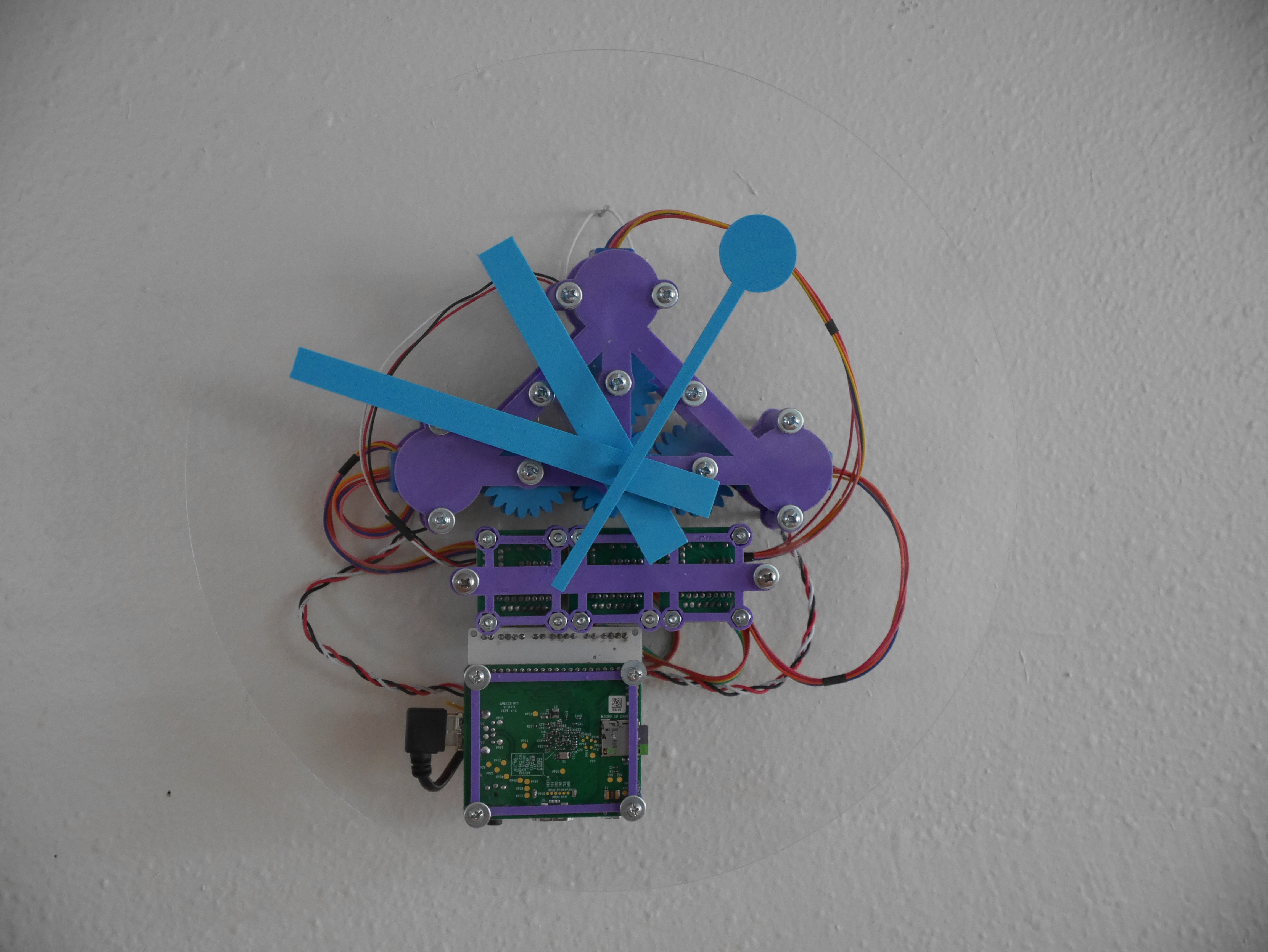
I went to TAP Plastics, my go-to retailer for all things plastic. I bought a 12″ diameter 3/8″ thick acrylic disc. Drilled some holes, and got to mounting this whole caboodle. This project is starting to take shape! With the help of a few colorful wires for extra flourish:
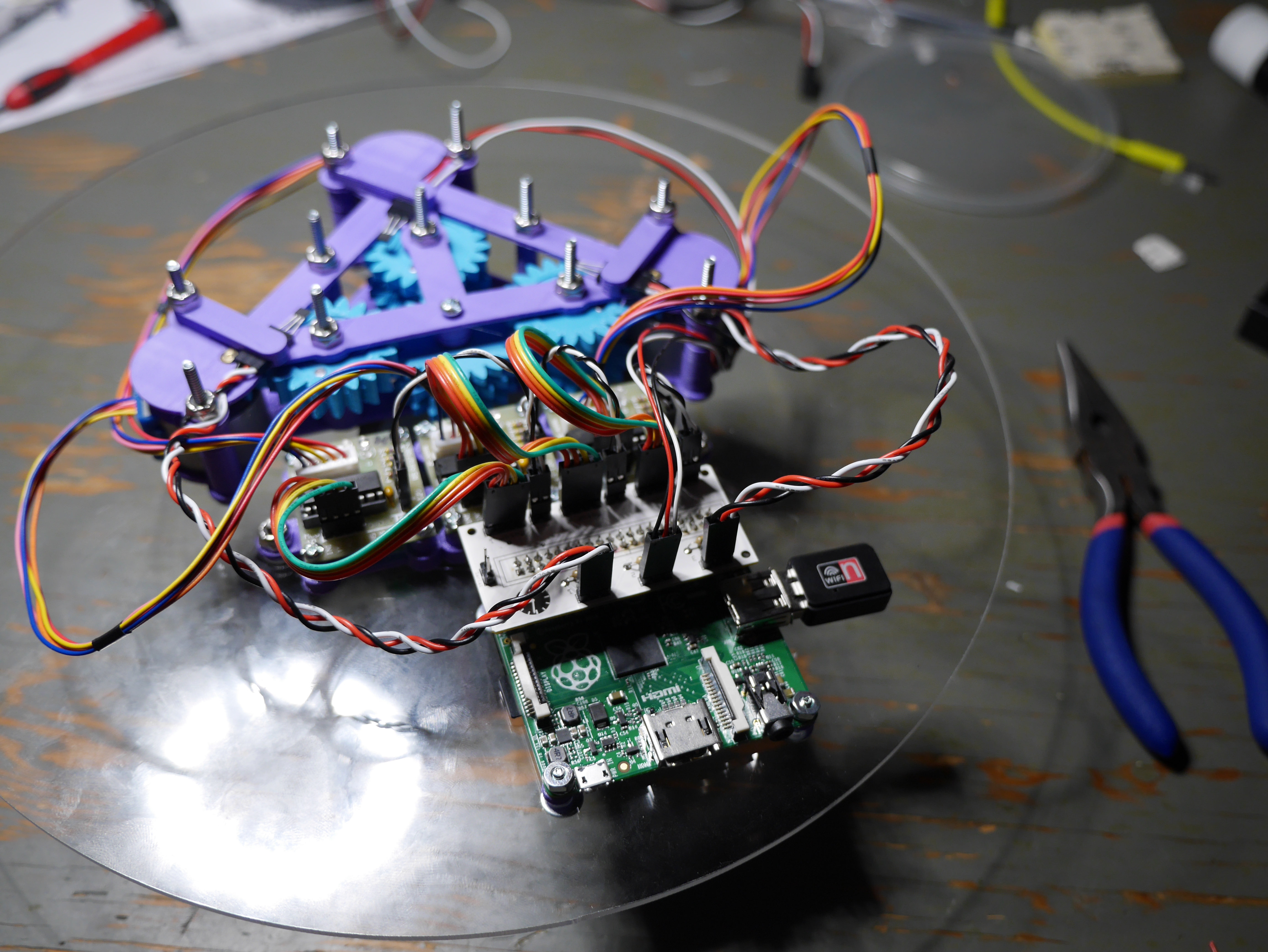 All the components mounted on the acrylic disc.
In Conclusion
The slick marketing from Apple and Samsung will have you believe that your life isn’t complete without their latest smart watch. They are wrong.
Your life isn’t complete because you haven’t built your own smart clock. Prime your soldering iron and get to work!